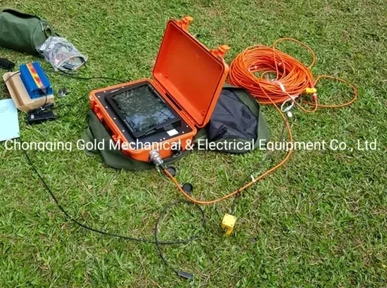
Sheffield sits at roughly 53.38 degrees north, where the River Don cuts through the Pennine foothills. The local geology shifts abruptly, Carboniferous sandstones and shales can give way to glacial till or alluvium within a few hundred metres. Projects around the Seven Hills often encounter weathered mudstone at shallow depth, which makes seismic velocity profiling essential before excavation. Seismic tomography maps these transitions by measuring how compressional and shear waves travel through the subsurface. The method works well in the city’s mixed terrain, from the steep slopes of Crookes to the flatter industrial land along the Don Valley. MASW surveys can complement the refraction data to derive shear-wave velocity profiles where site classification is required. For deeper targets, seismic refraction provides a cost-effective first look at bedrock topography under variable overburden.
A single seismic line across the Loxley Valley can reveal a buried channel filled with soft alluvium that boreholes alone might miss.
Local geotechnical context
Two sites barely a mile apart in Sheffield can tell completely different stories underground. A project on the sandstone ridge in Fulwood might encounter competent rock at 2 metres, while a site near Kelham Island, built on River Don alluvium, can hide 8 metres of soft silts above a weathered shale bedrock. Missing that contrast leads to unexpected excavation conditions, over-ordered concrete, or worse, differential settlement under shallow foundations. Seismic tomography reduces this uncertainty by imaging the velocity contrast between loose drift and competent bedrock before a single bucket enters the ground. In former industrial zones, the method can also flag backfilled cellars or old culverts, hazards that standard borehole logs sometimes skip. The data feeds directly into ground models and helps structural engineers decide between pad footings, piles, or ground improvement before the cost spiral begins.
Questions and answers
How deep can seismic tomography investigate on a typical Sheffield site?
Refraction surveys with a weight drop or accelerated weight drop source routinely reach 30 to 40 metres in the local geology. Reflection profiling can image targets beyond 100 metres, depending on the acoustic contrast and surface conditions.
What is the cost range for a seismic refraction survey in Sheffield?
A typical single-line refraction survey with 24 or 48 geophones falls between £1,940 and £4,190, depending on line length, access constraints, and the energy source required. Multi-line or 3D grid surveys are quoted on a project-specific basis.
Can the survey be done on tarmac or concrete surfaces without breaking the ground?
Yes. Geophones are coupled to the surface using a thin layer of sand or plasticine on hardstandings. Shear-wave sources need better coupling, but standard P-wave refraction works reliably on tarmac, concrete, and compacted gravel.
How does seismic tomography fit into a BS 5930 ground investigation?
It is used as a reconnaissance tool to optimise intrusive investigation. The velocity model guides borehole and trial pit locations, identifies zones of deep weathering, and provides continuous profile data between discrete sampling points, satisfying BS EN 1997-2 requirements for geophysical methods.